Our goal here is to create a simple identity mapping across the entire address space between virtual and physical memory addresses – such that the following formula holds true:
| 1 | virtual address = physical address |
In other words, the address space from the processor’s point of view (or anyone else’s POV for that matter) will remain the same both before and after the MMU has been switched on.
This goal may seem a little pointless – but it does act as a good starting point for further development. For example, you can start to make use of other features of the MMU such as specifying access permissions and attributes of pages.
When an MMU is in use it is able to automatically convert virtual addresses to physical addresses – however in order to do this it extensively utilises (at a performance cost) a set of translation tables (sometimes known as page tables) stored in physical memory. Therefore prior to enabling the MMU these tables must be appropriately set up and the hardware must be told where in memory they can be found. The translation tables are typically set up very early on during boot by an operating system.
The ARM MMU supports entries in the translation tables which can represent either an entire 1MB (section), 64KB (large page), 4KB (small page) or 1KB (tiny page) of virtual memory. In order to provide flexibility the translation tables are multi-level – there is a single top-level table which divides the address space into 1 MB sections and each entry in that table can either describe a corresponding area of physical memory or provide a pointer to a second level table. Depending on the type of second level table pointed to – that megabyte of memory can be then be represented by multiple table entries describing memory areas of the other page sizes (and even mixed). As the tables are multi-level the lookup process performed by the MMU is often known as a translation table walk.
The ARM MMU table design is rather clever in that it allows you to mix and match page sizes – if this wasn’t the case then you would have to choose a single page size to work with which may come at the expense of the amount of RAM required to store the page tables. For example if the entire address space was represented by tiny pages of 1KB then the translation table would take up a massive 16MB of memory (sizeof(page table entry) / 1KB) * sizeof(address space)).
Besides the amount of storage required for page tables, when considering which page sizes to use – performance should also be a consideration – when the hardware performs a translation table walk it has to access physical memory at least once which is relatively slow. Thankfully the MMU has a dedicated cache for making a note of recent translations – it’s known as a Translation Lookaside Buffer (TLB).
Now let’s get on with some coding! As we wish to write the least amount of code possible – we will only utilize the first level page table. As we are creating an identity mapping we will populate each entry in the table (therefore 4096 entries) which points to a corresponding range of physical memory with the same address. We start by telling the TLB the base address of our table. How about this:
So we start of (within our well-defined point of entry ‘start’) by loading the memory address 0x40200000 into register r0. We intend for this to represent the start of our first level page table. As we know page table entries in this table are 4 bytes long and that there is a maximum of 4096 entries (one for each 1MB of the address space) we can calculate the size of the table as 16KB. I’ve decided to locate this at the start of the available SRAM – of course, if you wanted to write more code you could first initialise your SDRAM controller and place the page tables in SDRAM instead. (Please note the hardware also demands that the table is located on a 16KB boundary).
The next line of source uses an ‘mcr‘ instruction to inform the TLB of our chosen location for the top level page table. The MMU/TLB is treated as a coprocessor to the ARM and as a result, the ‘mcr‘ and ‘mrc‘ instructions must be used to pass register values to and from coprocessor registers. In this case, we’re telling the ARM to transfer the value stored in r0 to register 2 of coprocessor 15 (as specified by the ARM architecture reference manual – see section B3.7 for more details).
The next step is to populate the tables. As we only intend to use the first level table we are constrained to either filling the table with ‘section’ entries or ‘page faults’ (entries which will always cause a page fault). Section entries represent an entire 1MB region of memory and have the following layout.
| 1 | Bits 31:20 – Section base address |
| 2 | Bits 11:10 – Access permissions |
| 3 | Bits 8:5 – Domain |
| 4 | Bit 3:2 – Cachable / Bufferable |
| 5 | Bits 1:0 – Always 0b10 for a section page table entry / descriptor |
Some bits are missing – these are bits which are either not used and should always be set to zero or ‘implementation defined’ – which means that it’s up to the ARM licensee to decide what to do with them – we will keep them at zero. The lower couple of bits is set to 0x2 which describes the entry as a section descriptor.
We’re most interested in the ‘Section Base Address’ – when the MMU wants to translate a virtual address – it finds the corresponding page table entry representing that range of virtual memory in the section table and substitutes the top 12 bits of the virtual address with the Section Base Address. For example, if we set the value 0x1f2 as a Section Base Address in the second entry of the table then all we will get a translation scheme (just for that 1MB of memory) which looks like this:
| 1 | 0x001xxxxx (virtual) = 0x1f2xxxxx (physical) |
Therefore to create an identity mapping – the values we need to use for the Section Base Address need to start with 0x000 for the first entry and increment by 1MB (or 0x1) each time.
| 1 | 0x000xxxxx (virtual) = 0x000xxxxx (due to entry 0) |
| 2 | 0x001xxxxx (virtual) = 0x001xxxxx (due to entry 1) |
| 3 | 0x002xxxxx (virtual) = 0x002xxxxx (due to entry 2) |
| 4 | … |
| 5 | 0xfffxxxxx (virtual) = 0xfffxxxxx (due to entry 4096) |
In order to create these tables we would need to write a loop – however in order to simplify this blog post – I’m just going to manually create entries for the page ranges which I intend to use (which isn’t many) – I end up with this:
| 1 | ldr r0, entry4020 |
| 2 | ldr r1, val4020 |
| 3 | str r1, [r0] |
| 4 | |
| 5 | entry4020: |
| 6 | .word 0x40201008 |
| 7 | val4020: |
| 8 | .word 0x40200c02 |
Let’s examine this. As my application is just a tight loop – it doesn’t have many memory access requirements – as it doesn’t use a stack or any peripherals all it needs to access is the address containing those instructions – thus ‘mapping in’ the entire SRAM area will be sufficient. My code writes the value 0x40200c02 to 0x40201008 – the destination address is the offset in the page table which corresponds to the 1MB of memory which includes the SRAM (table base + 0x402 * 4). The value I’m writing to this address is our first section page table entry. The top 12 bits – the Section Base Address – matches that of the virtual address corresponding with this table entry – thus an identity. The remaining bits are set appropriately to allow us to access the page.
There is one more concept we need to understand – Domains – but we will skim over these. Every page table entry is associated with a domain (just a number) – each domain has an attribute which allows you to control access to it’s associated pages. It’s a good way of quickly disabling access to a whole range of pages without having to modify the access permissions of each page entry. In our example we assigned the page table entry to domain 0. We now need to set the access permissions for that domain – we will set it to ‘Manager’ – which means access permissions are not checked – i.e. turn it off. This is achieved through another coprocessor access:
| 1 | mov r0, #0x3 |
| 2 | mcr p15, 0, r0, c3, c0, 0 |
If you are still with me – it’s now time to turn on the MMU. If your mappings change the address of the code ‘you are standing on’ (which is a bad idea) – then you have to make sure that your code is compiled to be position independent – such that it can ‘carry on’ at it’s new address. Thankfully as we are just using an identity mapping we don’t need to worry about this.
| 1 | mrc p15, 0, r0, c1, c0, 0 |
| 2 | orr r0, r0, #0x1 |
| 3 | mcr p15, 0, r0, c1, c0, 0 |
Let’s see what’s going on here. The three lines of code read the value from coprocessor register 1 of p15, modify that value and write it back. Register 1 contains lots of interesting things – such as where the exception table lives, if the caches are enabled and of course bit 0 determines if the MMU is enabled or not. In this case, we set it and thus turn on the MMU.
In my source I also added a tight loop after enabling the MMU in the absence of anything else useful to do…
| 1 | loop: |
| 2 | b loop |
That’s all the code complete – we can build using the following commands:
| 1 | arm-none-linux-gnueabi-gcc mmu.s -nostdlib -e start -Ttext=0x40204000 |
| 2 | arm-none-linux-gnueabi-objcopy -O binary a.out a.bin |
| 3 | ./signGP a.bin 0x40204000 |
| 4 | mv a.bin.ift MLO |
You may notice that I’ve set the link address (and thus entry point) to be 16KB into the SRAM area (0x40204000) – in other words just after our page tables.
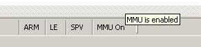
If you compile and execute the code on your BeagleBoard and all has gone well then you should find your BeagleBoard is stuck in the last loop after enabling the MMU.
If it hasn’t gone too well – then you’re probably seeing data or instruction aborts (exceptions). It may take a number of attempts to get right thus it’s probably a good idea to use a debugger and set break points in your exception handlers.
If you reached the tight loop (running with the MMU enabled) then congratulations you have successfully managed to turn on the MMU and live to tell the tale!
First publication date : 07/27/2011 by Embedded Bits